Why GOLD BLINGKING Engineers PVD Evaporation Coating Equipment for Wide Chambers
Uniform Thickness Across the Whole Surface
A large substrate enters the chamber. The operator expects identical film thickness at every point. Center thickness often differs from edge thickness in poorly designed systems. PVD evaporation coating equipment faces this physical challenge daily. The evaporation source releases atoms in a directional plume. Parts positioned away from the source center receive fewer atoms. How does production equipment compensate for this natural unevenness? jbczn answers through source geometry, substrate motion, and chamber arrangement.
The evaporation plume follows a cosine distribution pattern. Most atoms travel straight up from the source surface. Fewer atoms move at shallow angles toward the sides. A stationary substrate directly above the source receives a thick center patch. The same substrate's edges collect thinner material. This cosine loss creates unacceptable variation for large parts. An optical filter cannot function with a ten percent thickness change across its surface. Decorative coating suffers visible color shift from center to perimeter.
Source placement solves part of this problem. Multiple evaporation sources arranged in a line create overlapping plumes. The center of each plume has high flux. The overlap regions receive combined flux from adjacent sources. Total deposition across the substrate becomes sum of contributions from all sources. A system with a single source cannot achieve this averaging effect. A linear source array transforms a peaked distribution into a flatter profile. Each source requires independent power control to balance its emission rate.
Substrate rotation provides the second uniformity tool. A rotating fixture carries the part through different regions of the evaporation plume. Every point on the substrate passes through high-flux and low-flux zones over time. The time‑average deposition equalizes across the entire surface. Planetary rotation systems add another layer of averaging. Each substrate rotates on its own axis while orbiting around a central axis. This complex motion ensures that every square centimeter sees identical flux history. Single‑axis rotation works for simple shapes. Complex geometries demand planetary systems. PVD evaporation coating equipment without rotation cannot achieve large-area uniformity regardless of source design.
Source-to-substrate distance trades off between deposition rate and uniformity. A source placed very close to the substrate produces strong cosine losses. The center receives many atoms. The edges receive few. Moving the source farther away reduces this difference. The plume spreads out before reaching the substrate. Center-to-edge thickness variation shrinks. However, distance reduces deposition rate. A farther source takes longer to reach target thickness. Designers select a distance that balances speed against uniformity requirements for each product type.
Chamber wall shielding affects thickness consistency. Material deposits on walls during evaporation. This buildup eventually flakes and creates particles. More importantly, wall deposits change the chamber's internal geometry over time. A shield covered with rough coating reflects atoms unpredictably. These reflections add uncontrolled flux to the substrate. Initial uniformity calculations assume clean walls. A dirty chamber invalidates those calculations. Regular shield replacement or cleaning restores predictable flux patterns.
Real‑time thickness monitoring closes the control loop. Quartz crystal monitors measure deposition rate at specific chamber locations. A single monitor cannot see the whole substrate. Multiple monitors placed at different radii provide feedback on radial uniformity. The control system adjusts source power or substrate rotation speed based on these signals. Closed‑loop control catches drift before thickness variation exceeds specification. A system without in‑situ monitoring relies on periodic test runs. Test runs catch problems after they have already produced non‑uniform batches.
jbczn applies these principles in every design. Their chambers include linear source arrays for wide substrates. Planetary fixturing handles three‑dimensional parts without shadowing. Adjustable source‑to‑substrate distance allows tuning for each product type. Multiple quartz crystal monitors feed real‑time uniformity data to the control system. A customer coating large plastic panels finds center‑to‑edge variation below one percent. Another processing optical filters maintains strict thickness windows across three hundred millimeters.
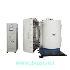
https://www.jbczn.net/product/evaporation-coating-equipment/horizontal-vacuum-evaporation-coating-equipment-for-plastic-products.html displays a system built for large‑area uniformity. The page avoids absolute thickness claims. Each specification includes the measurement location and method. Jinhua GOLD BLINGKING tests every chamber with witness samples placed at nine positions across the substrate holder. A system passes only when all nine samples fall within the target thickness range. One out‑of‑spec sample triggers a design review.
Uniform thickness does not happen by accident. It requires intentional geometry of sources, careful motion planning, clean chamber walls, and active monitoring. A system missing any of these elements produces edge‑to‑center variation that grows with substrate size. jbczn builds PVD evaporation coating equipment with all four uniformity tools. Why accept a coating that measures thin at one edge and thick at the opposite corner?